NORELEM
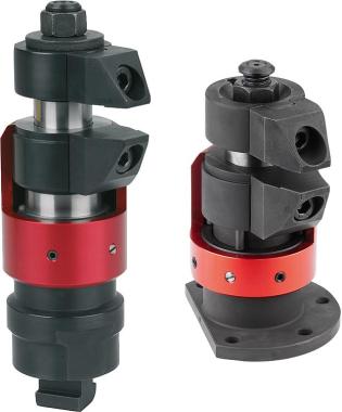
Compact double/single acting hydraulic swing clamp cylinder with spring return
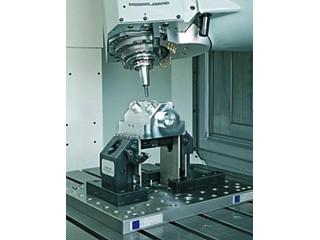
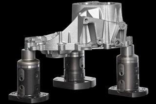
Compact swing clamps are designed for clamping devices where the clamping points must remain free during removal or insertion. They are also suitable for restricted installation spaces. Compact swing clamp cylinders operate as single or double acting pull cylinders. For compact swing clamp cylinders, there are three housing types to choose from as well as different actuation modes. The tightening movement is initiated by a superimposed pivoting and lifting movement. The effective clamping stroke is carried out in a linear movement. Many variants are available with a swivel angle of 90° left or right.
Material: Steel body and piston.
NBR seal. Finish: Burnished body.
Hardened piston. Note: If the admissible volumetric flow rate is exceeded at the level of the swivel clamping cylinder, a flow reducer must be inserted.
The permissible operating pressure of the swing clamp cylinders depends on the length of the clamp arms.
When assembling the clamping arms, they must be held in place so as not to damage the ball guide of the swivel clamping cylinders.
Depending on the ventilation connection, the sintered filter of the single-acting swing clamp cylinders must be replaced by a threaded plug.
Clamp arm for compact swing clamp cylinder is not included.
Observe safety instructions. Instructions for use: - Threaded connection
- Flange connection with O-ring.
- Drilled channels. Technical data: Max. operating pressure. : 350 bar. Assembly: See assembly outline. Advantages: - Compact shape
- Many versions.
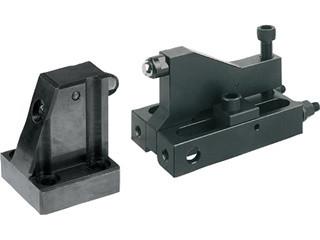
- Collision-free access to the workpiece. On request: Larger strokes and piston diameters, other swivel angles, different clamping arm supports, with optional position control. Accessories: Clamping arm for compact swivel clamping cylinder 04368-10. Scope of delivery - 1 slotted nut M27x1.5 (only for compact swing clamps 04368-14081104190100, 04368-14081104190200, 04368-14062104190100, 04368-14062104190200 ).
- 1 screw or nut for clamping arm support. Drawing indication:
AOF form: flange at top, Flange connection with O-ring
Form BGW: flange at the bottom, threaded connection
BOF form: flange at the bottom, Flange connection with O-ring
Form C: threaded connection



 Français


